


Hardware components | ||||||
_wzec989qrF.jpg?auto=compress%2Cformat&w=48&h=48&fit=fill&bg=ffffff) |
| × | 1 | |||
| × | 1 | ||||
| × | 1 | ||||
 |
| × | 1 | |||
Software apps and online services | ||||||
 |
| |||||
Since the building of our house, we had a lot of water in the foundation, sometimes about 40-50 m3 of water. So I have made a system under the house that lead the water to a sump with a submersible pump. The pump was needed because the sewerage level was higher then the level of water in the foundation. At a certain level the sump is emptied by pumping the water automatically to the sewerage. The submersible pump has a floating switch and works autonomous. I was curious how it was working or better; is it working? Seems that he was doing his work, because there was no longer water in the foundation.... but to verify, I had to open a hatch. Lot of stupid work. So years ago I build a system with "conventional" components. The system counted the times of the operation of the pump. Even a time-out was present when the pump was working longer then 3 minutes; something must be wrong with the pump. From the number of operations it was possible to see if the pump was working frequently or -maybe- is out of order...?
The old stuff and the new submersible pump control.
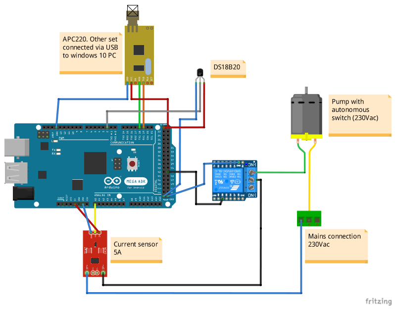
The new control is build with an Arduino MEGA2560, a Hall element for measuring the current of the well pump and an APC220 transmitter for the communication with the PC. The APC220 is used because of the distance between the control and the PC. The distance is more than 20m and not ideal for Bluetooth. RF is better and an APC220 set is working perfect. When the well pump is active, this action is processed by the Arduino board. In most cases the pump operates for 45 sec to pump all the water from the sump to the sewerage. For reporting and get ride of possible disturbances, the indication of the pump must be present for at least 5 seconds. When the pump is active for more then 10 minutes, the pump is blocked (by a relay) and must be reset to operate again (reset button or via the supervisory and control standard Visual Studio application). What a pleasure working with the standard Visual Studio application! Communication ready to roll, masking, forcing and trending of the signals is ideal and gives a lot of efficiency during building and debugging the application.
Click here for the UserConfiguration and here for the UserFiniteStateMachine. Remark: UserConfiguration and UserFiniteStateMachine are the user parts of the Standard Finite State machine.
Remark: You can download the Windows 10 and Raspberry version of the debugger from my website. The raspberry version of the debugger lacks the graphical plotter. Read all about the debuggers on the website!
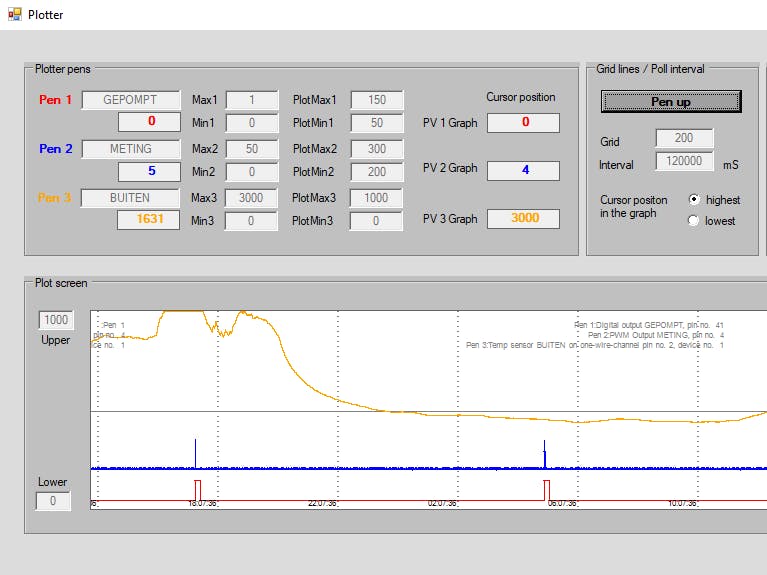
Below a picture of the standard windows debug application for this application. Data (of the bold process values) is logged to an access database.
Plotter example: the spikes in the graph represent an active submersible pump. The orange pen is a DS18B20 temperature sensor, also connected to the board.
The result (what counts...), no water....
// V38 Standaard Arduino application by J.B. Siemonsma
// Copyright  Wytgaard 2015
//
//   MM          MM   EEEEEEEEEE     GGGGGGGG        AAAAAA
//   MMMM      MMMM   EE           GGG      GG      AA    AA
//   MM  MM  MM  MM   EE          GG               AA      AA
//   MM    MM    MM   EEEEEE      GG      GGGGGG  AA        AA
//   MM          MM   EE          GG          GG  AAAAAAAAAAAA
//   MM          MM   EE           GGG      GGG   AA        AA
//   MM          MM   EEEEEEEEEE     GGGGGGGG     AA        AA
//
// Supporting:
// - hardware Arduino MEGA 2560
// - initialization of digital inputs (pullup used, so switch to gnd)
// - initialization of digital ouputs
// - initialization of analog inputs
// - initialization of analog outputs (PWN, puls width modulation)
// - initialization of servos
// - Visual control of a working/checked configuration (Flashing LED PIN 13)
// - Help functions in the serial monitor (use "h" for help)
// - cyclic reading of defined digital inputs, with current status, timestamp, change notification; e.g. usefull for phase transitions;
//   if the status of an input changes in cycle n, it is notified by field "changed", cycle n+1, the field "changed" is reset again.
// - cyclic reading of defined analog inputs
// - calculated cycle time, can be visualised in the help function
// - asynchronous timer function, waiting without using "delay" function. Made up by pointerstructure.
// - function for setting digital outputs
// - function for setting analog outputs
// - example of interrupt handling (see also , loop and the Isr function)
// - available functions to determine and check bits by there tagname
// - available functions to determine and check analogue values by there tagname
// - available function to send messages by I2C (e.g. to the SMS Alarm sketch or the LCD display sketch).
// - serial communication for HMI functionality, see also the documentation
// - RTC, Real time clock for setting the system time
// - One wire channel for reading e.g. temperature(s)
//
// Upcoming features
// - PID regulator
//
// Available USER functions
// - digitalClockDisplay(), present the current time
// - InputOverview(), present an overview of all defined digital input pins
// - OutputOverview(), present an overview of all defined digital output pins
// - AnaInOverview(), present an overview of all defined analog input pins (digital value and calculated voltage, 0-5 Volts)
// - AnaOutOverview(), present an overview of all defined analog output pins (digital value and calculated voltage, 0-5 Volts)
// - boolean Timer (unsigned long Time, int TimerNo ), Start/check a timer, when the timer not exists (# not known) it will be created,
//   when expired it will return true and the timer -pointer entries- will be deleted. The timer works asynchronous, not delaying the loop.
// - boolean CancelTimer (int TimerNo ), When a timer is not needed anymore, use this function to cancel the timer to prevent not wanted actions
// - Isr (), Example of an Interrupt Service Routine. The Isr call is defined in the setup part. In this particular case it is called by the rising edge of pin 20,
//   Beware: Variables used in the Isr must be declared volatile. In de main loop they must be copied to local varables for processing/printing while interrups disabled. See the example in the loop part.
// - boolean DigRising ( String Tag ), Determine by tagname the bit-rising event
// - boolean DigFalling ( String Tag ), Determine by tagname the bit-falling event
// - boolean DigLow ( String Tag ), Determine by tagname the bit low status
// - boolean DigHigh ( String Tag ), Determine by tagname the bit high status
// - boolean Activate (String Tag ), Set the digital output by tagname, there is no deactivate function, this is always done in de main loop (Fonterra strategie)
// - int AnaValue ( String Tag ), returns the analogue value of tagname
// - int Distance ( String Tag ), returns the distance in cm of tagname
// - boolean AnaBetween (String Tag, int LowVal, IntHighVal), determine by tagname
// - boolean AnaLower (String Tag, int LowVal), determine by tagname
// - boolean AnaHigher (String Tag, Int HighVal), determine by tagname
// - boolean AnaGoUnder (String Tag, int LowVal), determine by tagname
// - boolean AnaGoOver (String Tag, Int HighVal), determine by tagname
// - boolean DistanceBetween ( String Tag, int LowVal, int HighVal ), determine by tagname
// - boolean DistanceShorter ( String Tag, int LowVal ), determine by tagname
// - boolean DistanceLonger ( String Tag, int HighVal ), determine by tagname
// - boolean UpdateAna (String Tag, Value ), set the analog output by tagname
// - boolean UpdateServo (String Tag, Angle), control servos by tagname
// - MessageI2C(String Message), send a message to slave 9 by I2C. Use the SlaveCommunicator sketch
//   to read the message and present it -for example- on a LCD display.
// - Support for HMI. Cummunication by message from HMI. See the discription.
//
//
//
// All included libraries and constants, do not remove or change
//
//#include <PID_v1.h>
#include "UserConfiguration.h"
#include <TimeLib.h>
#include <RTClib.h>
#include <NewPing.h>
//#include <Time.h>
#include <Servo.h>
#include <Wire.h>
#include <MemoryFree.h>
#include <OneWire.h>
#include <DallasTemperature.h>
//
#define TIME_MSG_LEN       11  // time sync to PC is HEADER followed by unix time_t as ten ascii digits
#define TIME_HEADER        'T' // Header tag for serial time sync message
#define TIME_REQUEST       7   // ASCII bell character requests a time sync message

#define StartDigitalPins   22  //Start of the pin layout for the Digital pins
#define EndDigitalPins     53  //End of the pin layout for the digital pins
boolean LayoutDigital[EndDigitalPins - StartDigitalPins + 1]; //Check array digital pins

#define StartPWMPins        2  //Start of the pin layout for the PWM pins
#define EndPWMPins          13 //End of the pin layout for the PWM Pins
boolean LayoutPWM[EndPWMPins - StartPWMPins]; // Check array PWM pins

#define StartAnalogInPins   0  //Start of the pin layout for the analogue in pins
#define EndAnalogInPins    15  //End of the pin layout for the analogue in pins
boolean LayoutAnalogInPins[EndAnalogInPins - StartAnalogInPins]; // check array analogue in Pins

//
// Predefined timer id's, do not remove!
//
const byte TimOneHour    = 200;
const byte TimISR        = 201;
const byte TimUS         = 202;
const byte TimTT         = 203;
const byte TimDelayGMI   = 204;
const byte TimHMIWtd     = 205;
const byte TimBlinking   = 206;
const byte TimBlinkWtdOn = 207;
const byte TimBlinkWtdOff= 208;
const byte TimGpsPoll    = 209;
//
// Temperature sensors. Do not remove.
//
byte OneWireBus = OneWireChannel;
OneWire oneWire(OneWireBus);
DallasTemperature sensors(&oneWire);
//
// Real time, type clock DS1307
RTC_DS1307 RealTimeClock;
////
//
// Interrupt Pin numbers (do not remove/change)
//int Pin2  = 0;
//int Pin3  = 1;
//int Pin21 = 2; SCL
//int Pin20 = 3; SCA
//int Pin19 = 4;
//int Pin18 = 5;
//
//reserved variables, do not remove/change
//
int                    Pin13    = 0;
int                    Blinking = 500;
byte                   incomingByte;
boolean                CConfigurationOK;
boolean                OnOff;
time_t                 tijd;
boolean                RTCAvailable;
unsigned long          CycleStart;
unsigned long          NoOfCycle;
boolean                CycleCalc;
boolean                CycleCalcHMI;
unsigned int           PWN_value;
String                 OldMessageI2C;
char                   WatchdogI2C = 5;
volatile unsigned long ISR_Count;
unsigned long          ISR_Count_Copy;
int                    Threads = 1;
int                    CurrentThread = 0;
int                    NoFSMStates = 0;
int                    MachineState = 0;
char                   Karakter = -1;
String                 KarakterString = "";
String                 GPSString = "";
int                    KarakterIndex = 0;
int                    Getal;
int                    NoHandTags = 0;
int                    NoMaskTags = 0;
String                 ValidationId;
String                 DummyCommands [] = {"DUMMY"};
String                 HMICommands [] = { "SDI", "SAI", "FDO", "FAO", "RTA", "PDI", "PAI", "CAN", "RDC", "GMI",
//                                           0      1      2      3      4      5      6      7      8      9
                                          "MDI", "MAI", "RMM", "FSM", "FSO", "WTD", "PMT", "FMT", "MTC", "THM",
//                                        	10     11     12     13     14     15     16     17     18     19
                                          "CLT", "RAM", "TIM", "JM0", "RDB", "CDB" };
//                                          20     21     22     23     24     25

int                    NoHMICommands = 25+1;
String                 GPSCommands[] = { "PUBX"};
//                                           0
int                    NoGPSCommands = 0 + 1;
char                   LF = 10;
char                   CR = 13;
boolean                DelayGMI = false;
boolean                HMIWatchDog;
unsigned long          HMIWatchDogTime;


struct FSMStateType
{
  String         FSMStateName;
  int            FSMStateNo;
  String         ActualState;
  boolean        Enter;
  boolean        Exit;
  int            ThreadNo;
  unsigned long  StartTime;
  unsigned long  TotalTime;
  struct         FSMStateType* Next;
};
FSMStateType FSMState;
FSMStateType* FSMStateKetting;
FSMStateType* FSMStateSchakel;

struct TimerType
{
  int           TimerId;
  unsigned long Initial;
  unsigned long Wait;
  boolean       State;
  struct        TimerType* Next;
  struct        TimerType* Previous;
};
TimerType TimerSchakel;
TimerType* TimerKetting;
TimerType* HuidigeSchakel;
TimerType* NieuweSchakel;
TimerType* VorigeSchakel;
int AantalSchakels;

struct MessageType
{
  String        Message;
  unsigned long SendTime;
  struct        MessageType* Next;
  struct        MessageType* Previous;
};
MessageType MessageSchakel;
MessageType* MessageKetting;
MessageType* HuidigeMessage;
MessageType* NieuweMessage;
MessageType* VorigeMessage;
MessageType* VolgendeMessage;

typedef struct DigInPinType
{
  int           Pin;
  boolean       Status;
  unsigned long TimeChange;
  boolean       Changed;
  String        Tagname;
  boolean       Report;
  boolean       Poll;
  unsigned long PollFreq;
  unsigned long PollTime;
  boolean       Mask;
  boolean       MaskValue;
  boolean       DBLogging;
};
DigInPinType InPin[NoInputPins + 1];

typedef struct DigOutPinType
{
  int           Pin;
  boolean       Status;
  boolean       PreStatus;
  unsigned long TimeChange;
  boolean       FixedStatus;
  boolean       Changed;
  String        Tagname;
  boolean       Report;
  boolean       Poll;
  unsigned long PollFreq;
  unsigned long PollTime;
  boolean       Auto;
  boolean       DBLogging;
} ;
DigOutPinType OutPin[NoOutputPins + 1];

typedef struct TempSensorType
{
  int           Channel;
  int           DeviceNr;
  float         Value;
  float         PrevValue;
  unsigned long TimeChange;
  boolean       Changed;
  String        Tagname;
  boolean       Poll;
  unsigned long PollFreq;
  unsigned long PollTime;
  boolean       Mask;
  boolean       DBLogging;
} ;
TempSensorType TempSensor[NoTemp + 1];

typedef struct AnaInPinType
{
  int           Pin;
  unsigned int  Value;
  unsigned int  PrevValue;
  unsigned long TimeChange;
  boolean       Changed;
  String        Tagname;
  boolean       Poll;
  unsigned long PollFreq;
  unsigned long PollTime;
  boolean       Mask;
  boolean       DBlogging;
} ;
AnaInPinType AnaInPin[NoAnaInPins + 1];

typedef struct AnaOutPinType
{
  int Pin;
  unsigned int  Value;
  unsigned int  PrevValue;
  unsigned long TimeChange;
  unsigned int  FixedValue;
  boolean       Changed;
  String        Tagname;
  boolean       Poll;
  unsigned long PollFreq;
  unsigned long PollTime;
  boolean       Auto;
  boolean       DBLogging;
} ;
AnaOutPinType AnaOutPin[NoAnaOutPins + 1];

typedef struct MyServoType
{
  int           Pin;
  int           Angle;
  Servo         MyServo;
  unsigned long TimeChange;
  int           FixedAngle;
  boolean       Changed;
  String        Tagname;
  boolean       Poll;
  unsigned long PollFreq;
  unsigned long PollTime;
  boolean       Auto;
  boolean       DBlogging;
} ;
MyServoType ServoPin[NoServos + 1];

typedef struct MyUltraType
{
  int           Trigger;
  int           Echo;
  int           MaxDistance;
  int           Distance;
  String        Tagname;
  boolean       Poll;
  unsigned long PollFreq;
  unsigned long PollTime;
  boolean       Mask;
  boolean       DBLogging;
} ;
MyUltraType Ultrasonic[NoUltrasonic + 1];

typedef struct MarkerType
{
  boolean       Status;
  boolean       PreStatus;
  boolean       FixedStatus;
  int           Value;
  int           FixedValue;
  int           PrevValue;
  String        TextString;
  String        PreTextString;
  unsigned long TimeChange;
  boolean       Changed;
  boolean       ChangedAnalogue;
  boolean       ChangedText;
  String        Tagname;
  boolean       Report;
  boolean       Poll;
  boolean       Auto;
  unsigned long PollFreq;
  unsigned long PollTime;
  unsigned long PollTimeAnalogue;
  unsigned long PollTimeText;
  boolean       DBLogging;
} ;
MarkerType Marker[NoMarkers + 1];

struct GPSType
{
  //NEO-6M Type with use of $PUBX commands
  String        UTC;           //2
  String        Latitude;      //3
  String        NSIndicator;   //4
  String        Longitude;     //5
  String        EWIndicator;   //6
  String        NavStat;       //8
  String        Hacc;          //9
  String        SOG;           //11
  String        COG;           //12
  String        GU;            //18
};
GPSType GPSdata;

//*******************************************************************************
//
//  Name: HMISendString
//
//  Modification date:
//  Changed by:
//
//  Function:
//  Send a message to HMI (via hardware communication channel 1)
//
//
//*******************************************************************************
void HMISendString ( String MessageToHMI )
{

  char LF = 10;
  char CR = 13;
  char Buffer[1000];
  int LenMessage;

  LenMessage = MessageToHMI.length();
  MessageToHMI.toCharArray(Buffer, 500);
  //Serial.println ( "@HMISendString (length:" + String(LenMessage) + "): >" + MessageToHMI + "<" );
  for (int index = 0; index < LenMessage; index++) Serial1.write(Buffer[index]);
  Serial1.write(CR);
  Serial1.write(LF);

}

//*******************************************************************************
//
//  Name: digitalClockDisplay
//
//  Modification date:
//  Changed by:
//
//  Function:
//  Print the current time on the serial monitor.
//
//
//*******************************************************************************
void digitalClockDisplay()
{
  // digital clock display of the time
  Serial.print(hour());
  printDigits(minute());
  printDigits(second());
  Serial.print(" ");
  Serial.print(day());
  Serial.print(" ");
  Serial.print(month());
  Serial.print(" ");
  Serial.print(year());
  Serial.println();
}

//*******************************************************************************
//  Name: LeadingZero
//
//  Modification date:
//  Changed by:
//
//  Function:
//  Return a string of 4 characters, with leading zero's.
//  Input an unsigned integer
//
//
//*******************************************************************************
String LeadingZero ( unsigned int Value )
{

  String Leading;
  String StrValue;

  StrValue = String ( Value );
  if (Value < 10 ) Leading = "0";
  if (Value < 100 ) Leading = Leading + "0";
  if (Value < 1000 ) Leading = Leading + "0";
  StrValue = Leading + StrValue;
  return StrValue;

}

//*******************************************************************************
//
//  Name: PrintDigits
//
//  Modification date:
//  Changed by:
//
//  Function:
//  Print semicolon and a leading zero on serial monitor, input is an integer
//
//
//*******************************************************************************
void printDigits(int digits)
{
  // utility function for digital clock display: prints preceding colon and leading 0
  Serial.print(":");
  if (digits < 10)
    Serial.print('0');
  Serial.print(digits);
}

//*******************************************************************************
//
//  Name: processSyncMessage
//
//  Modification date:
//  Changed by:
//
//  Function:
//  When there is a unix time stamp from the serial monitor available,
//  set the time on the board. When a RTC available, set also the time on the
//  real time clock.
//
//
//*******************************************************************************
void processSyncMessage() {
  // if time sync available from serial port, update time and return true
  while (Serial.available() >=  TIME_MSG_LEN ) { // time message consists of header & 10 ASCII digits
    char c = Serial.read() ;
    //Serial.print(c);
    if ( c == TIME_HEADER ) {
      time_t pctime = 0;
      for (int i = 0; i < TIME_MSG_LEN - 1; i++) {
        c = Serial.read();
        if ( c >= '0' && c <= '9') {
          pctime = (10 * pctime) + (c - '0') ; // convert digits to a number
        }
      }
      setTime(pctime);
      if (RTCAvailable)
        {
		RealTimeClock.adjust(pctime);
		//RTC.set(pctime);
        //Serial.println ( F("%INF-RTC-CTC, RTC is also updated"));
        }
    }
  }
}

//*******************************************************************************
//
//  Name: InitFSMStates
//
//  Modification date:
//  Changed by:
//
//  Function:
//  Set the pointer structure for the FSM states. See also the documentation
//  for information about FMS states. Set the default states for the FSM's on
//  HIB (hibernate).
//
//
//*******************************************************************************
void InitFSMStates ()
{

  int StateNo = 0;
  FSMStateType* FSMStateLaatste;

  Serial.println ( F("Setup FSM States"));
  NoFSMStates = sizeof(PossibleFSMStates) / 6;

  while (StateNo < NoFSMStates)
  {
    // Build the state list..
    if ( FSMStateKetting == 0 )
    {
      // Chain doesn't exists yet
      FSMStateKetting = new FSMStateType;
      FSMStateKetting->FSMStateName = PossibleFSMStates [StateNo];
      FSMStateKetting->FSMStateNo = StateNo + 1;
      FSMStateKetting->ActualState = "HIB";
      FSMStateKetting->ThreadNo = 0;
      FSMStateKetting->StartTime = 0;
      FSMStateKetting->TotalTime = 0;
      FSMStateKetting->Next = 0;
      FSMStateLaatste = FSMStateKetting;
    }
    else
    {
      FSMStateSchakel = new FSMStateType;
      FSMStateSchakel->FSMStateName = PossibleFSMStates [StateNo];
      FSMStateSchakel->FSMStateNo = StateNo + 1;
      FSMStateSchakel->ActualState = "HIB";
      FSMStateSchakel->ThreadNo = 0;
      FSMStateSchakel->StartTime = 0;
      FSMStateSchakel->TotalTime = 0;
      FSMStateSchakel->Next = 0;
      FSMStateLaatste->Next = FSMStateSchakel;
      FSMStateLaatste = FSMStateSchakel;
    }
    ++StateNo;
  }

  //Going trough the chain....
  FSMStateSchakel = FSMStateKetting;
  do
  {
    Serial.println ( "State " + FSMStateSchakel->FSMStateName + " (PID=" + String (FSMStateSchakel->FSMStateNo ) + "), current state = " + FSMStateSchakel->ActualState );
    FSMStateSchakel = FSMStateSchakel->Next;
  } while ( FSMStateSchakel != 0);

  Serial.println ( F("Setup FSM States ready"));
  Serial.println ( F("-------------------------------------"));
  Serial.println ( F(""));

} // End of InitFSMStates

//*******************************************************************************
//
//  Name: FSMStateOverview
//
//  Modification date:
//  Changed by:
//
//  Function:
//  Present an overview of the FSM states on the serial monitor.
//
//
//*******************************************************************************
void FSMStateOverview()
{

  String RunTime;

  Serial.println();
  Serial.print(F("FSM state overview at "));
  digitalClockDisplay();
  Serial.println(F("----------------------------------------- "));
  FSMStateSchakel = FSMStateKetting;
  do
  {
    if (FSMStateSchakel->StartTime == 0 )
    {
      RunTime = String ( FSMStateSchakel->TotalTime / 1000 );
    }
    else
    {
      RunTime = String ( ( FSMStateSchakel->TotalTime + millis() - FSMStateSchakel->StartTime ) / 1000 ) + "+";
    };
    Serial.println ( "State " + FSMStateSchakel->FSMStateName + " (PID=" + String (FSMStateSchakel->FSMStateNo ) + "), current state = " + FSMStateSchakel->ActualState + " in thread no. " + String (FSMStateSchakel->ThreadNo) + " Runtime: " + RunTime );
    FSMStateSchakel = FSMStateSchakel->Next;
  } while ( FSMStateSchakel != 0);
  Serial.println(" ");

} // End of FSMStateOverview;

//*******************************************************************************
//
//  Name: TransitionToState
//
//  Modification date:
//  Changed by:
//
//  Function:
//  - Find the current state in the active thread and put it on hibernate (HIB).
//  - Examine all existing threads and find the highest thread.
//  - Check the existens of the new statename.
//  - Put the new statename on state pending (PEN).
//  - If the name of the state is END do nothing.
//
//  Explanation of handling FSM states (most be documented somewhere...)
//
//  - Initial all states have the status HIB (hibernate)
//  - By calling TransitionToState, the state's status is changed to PEN (pending)
//    so the state is a candidate for executing the code in the main loop.
//  - At the end of the PLC cycle, all PEN (pending) states are put in RUN (running) state.
//    Also all states still on COM (computing) are put on RUN (running) again.
//  - In the new PLC cylce, all RUN (running) states are executed once and the status is
//    put on COM (computing). When TransitionToState is called in the active state,
//    the active state is put in HIB (hibernate).
//
//  - It is possible to have more FSM's executed in parallel. Just call
//    TransitionToState more than once from the active state. They are then devided
//    over more parallel Threads.
//  - It is possible to Kill a thread when calling the END state in TransistionToState.
//    Be aware that killing the only living thread will kill the FSM.
//
//*******************************************************************************
void TransitionToState ( String StateName )
{
  FSMStateType* Chain;
  boolean FSMStateNameFound = false;
  int CurrentThread;
  int HighThreadNo;
  unsigned long EndTime;

  // find the current state and put it on HIB
  Chain = FSMStateKetting;
  do
  {
    if (Chain->FSMStateNo == MachineState)
    {
      // Current state is found... put it on HIB
      Chain->ActualState = "HIB";
	  Chain->Exit = true;
      Chain->ThreadNo = 0;
      if (Chain->StartTime != 0)
      {
        Chain->TotalTime = Chain->TotalTime + millis() - Chain->StartTime;
        Chain->StartTime = 0;
      }
    if (UseHMISerial) HMISendString("@FSM," + String(Chain->FSMStateName) + ",HIB");
    }
    Chain = Chain->Next;
  } while ( Chain != 0);

  // What can happen now?
  // Look for States on RUN and find highest ThreadNo
  Chain = FSMStateKetting;
  HighThreadNo = 0;
  do
  {
    //State with status on RUN?
    if ((Chain->ActualState == "RUN" ) || (Chain->ActualState == "PEN" ))
    {
      Threads = Threads + 1;
      if (Chain->ThreadNo > HighThreadNo ) HighThreadNo = Chain->ThreadNo;
    };
    Chain = Chain->Next;
  } while ( Chain != 0);
  HighThreadNo = HighThreadNo + 1;

  // To be sure, check if StateName is known...
  Chain = FSMStateKetting;
  do
  {
    //State with status on PEN and ThreadNo is set, except for END (=do Nothing)
    if (Chain->FSMStateName == StateName ) FSMStateNameFound = true;
    Chain = Chain->Next;
  } while ( Chain != 0);
  if (!FSMStateNameFound) Blinking = 1000;

  // ThreadNo is determined and now we can set the new state on PEN
  Chain = FSMStateKetting;
  do
  {
    //State with status on PEN and ThreadNo is set, except for END (=do Nothing)
    if ((Chain->FSMStateName == StateName ) && ( StateName != "END") && (Chain->ActualState == "HIB"))
    {
      Chain->ThreadNo = HighThreadNo;
      Chain->ActualState = "PEN";
	  //extra check; when exit event is set, this must be done in this transition; so it's a call to this transistion to remain running.
	  //do nothing with the enter or exit event!
	  if (!Chain->Exit) Chain->Enter = true;
      Chain->StartTime = millis();
      if (UseHMISerial) HMISendString ( "@FSM," + String(StateName) + ",RUN" );
    };
    Chain = Chain->Next;
  } while ( Chain != 0);

} // End of TransitionToState

//*******************************************************************************
//
//  Name: CurrentState
//
//  Modification date:
//  Changed by:
//
//  Function:
//  Return the PID number of the running (RUN) state and change the actual state
//  to computing (COM)
//
//
//*******************************************************************************
int CurrentState()
{
  FSMStateType* Chain;
  int Action;
  boolean Stop;

  Action = 0;
  Chain = FSMStateKetting;
  do
  {
    if ((Chain->ActualState == "RUN"))
    {
      Chain->ActualState = "COM";
      Action = Chain->FSMStateNo;
      break;
    };
    Chain = Chain->Next;
  } while (( Chain != 0)) ;

  return Action;

} // End of CurrentState

//*******************************************************************************
//
//  Name: ComToRunState
//
//  Modification date:
//  Changed by:
//
//  Function:
//  Change a computing (COM) or pending (PEN) state to running state(RUN).
//
//
//*******************************************************************************
void ComToRunState()
{
  FSMStateType* Chain;
  int Action;

  Action = 0;
  Chain = FSMStateKetting;
  do
  {
    if ((Chain->ActualState == "COM") || (Chain->ActualState == "PEN"))
    {
      Chain->ActualState = "RUN";
    };
    Chain = Chain->Next;
  } while ( Chain != 0) ;

} // End of ComToRunState


//*******************************************************************************
//
//  Name: FiniteState
//
//  Modification date:
//  Changed by:
//
//  Function:
//  Return the PID number of the CurrentState
//
//
//*******************************************************************************
int FiniteState ( String CurrentState )
{
  FSMStateType* Chain;
  int Action;

  Action = 0;
  Chain = FSMStateKetting;
  do
  {
    if (Chain->FSMStateName == CurrentState)
    {
      Action = Chain->FSMStateNo;
    };
    Chain = Chain->Next;
  } while ( Chain != 0) ;

  return Action;

}

//*******************************************************************************
//
//  Name: EnterState
//
//  Modification date:
//  Changed by:
//
//  Function:
//  Return true when entering the state the first time and reset the enter event
//
//
//*******************************************************************************
boolean EnterState()
{
	FSMStateType* Chain;
	boolean Action;

	Action = false;
	Chain = FSMStateKetting;
	do
	{
		if (Chain->FSMStateNo == MachineState)
		{
			Action = Chain->Enter;
			Chain->Enter = false;
		}
		Chain = Chain->Next;
	} while (Chain != 0);

	return Action;

} //EnterState


  //*******************************************************************************
  //
  //  Name: ExitState
  //
  //  Modification date:
  //  Changed by:
  //
  //  Function:
  //  Return true when leaving the state and reset the exit event
  //
  //
  //*******************************************************************************
boolean ExitState()
{
	FSMStateType* Chain;
	boolean Action;

	Action = false;
	Chain = FSMStateKetting;
	do
	{
		if (Chain->FSMStateNo == MachineState)
		{
			Action = Chain->Exit;
			Chain->Exit = false;
		}
		Chain = Chain->Next;
	} while (Chain != 0);

	return Action;

} //ExitState


//*******************************************************************************
//
//  Name: InitInputs
//
//  Modification date:
//  Changed by:
//
//  Function:
//  Initialize all digital input tags. Default INPUT_PULLUP. So not connected
//  the pins are high.
//
//
//*******************************************************************************
void InitInputs ()
{
  Serial.println ( F("Setup inputs"));
  Serial.println ( String("No. of inputs ") + String(NoInputPins));
  for (int InputIndex = 1; InputIndex <= (NoInputPins); InputIndex++)
  {
    InPin[InputIndex].Pin = FirstInput + InputIndex - 1;
    pinMode(InPin[InputIndex].Pin, INPUT_PULLUP );
    InPin[InputIndex].Status = digitalRead (InPin[InputIndex].Pin);
    InPin[InputIndex].Changed = 0;
    InPin[InputIndex].Poll = false;
    InPin[InputIndex].Mask = false;
    InPin[InputIndex].TimeChange = millis();
    InPin[InputIndex].Tagname = InputTags[InputIndex - 1];
	InPin[InputIndex].DBLogging = false;
	Serial.println ( "Init " + String (InPin[InputIndex].Tagname) + " #" + String ( InPin[InputIndex].Pin ) );
  }
  Serial.println ( F("Setup inputs ready"));
  Serial.println ( F("-------------------------------------"));
  Serial.println ();

} // End of InitInputs

//*******************************************************************************
//
//  Name: InitMarkers
//
//  Modification date:
//  Changed by:
//
//  Function:
//  Initialize all markers tags.
//
//
//*******************************************************************************
void InitMarkers ()
{
  Serial.println ( F("Setup markers"));
  Serial.println ( String("No. of Markers ") + String(NoMarkers));
  for (int Index = 1; Index <= (NoMarkers); Index++)
  {
    Marker[Index].Status = 0;
	Marker[Index].PreStatus = 0;
	Marker[Index].FixedStatus = 0;
	Marker[Index].TextString = "";
    Marker[Index].Changed = 0;
	Marker[Index].ChangedAnalogue = 0;
	Marker[Index].ChangedText = 0;
	Marker[Index].Auto = true;
    Marker[Index].Poll = false;
    Marker[Index].Report = false;
    Marker[Index].TimeChange = millis();
    Marker[Index].Tagname = MarkerTags[Index - 1];
	Marker[Index].DBLogging = false;
    Serial.println ( "Init " + String (Marker[Index].Tagname) );
  }
  Serial.println ( F("Setup markers ready"));
  Serial.println ( F("-------------------------------------"));
  Serial.println ( F(""));

} // End of InitMarkers


//*******************************************************************************
//
//  Name: InitUltrasonics
//
//  Modification date:
//  Changed by:
//
//  Function:
//  Initialize all ultrasonic devices. Each ultrasonic devices uses 2 digital
//  pins. The first is the trigger pin, the next the echo pin.
//
//
//*******************************************************************************
...

This file has been truncated, please download it to see its full contents.
// UserConfiguation.h
//
//
//*========================================================================================
//*========================================================================================
//*============  START USER CONFIGURATION FOR THE I/O   ===================================
//*========================================================================================
//*========================================================================================
//
// Define all used pins for the application.
//
// The range of digitals is commenly used. First to define the inputs,outputs and ultrasonics.
// The analog out en servo pins are in the PWN range of the board.
//
const byte NoInputPins    =  1;
const byte FirstInput     = 30;
const byte NoOutputPins   =  5;
const byte FirstOutput    = 40;
const byte NoUltrasonic   =  0;
const byte FirstUltra     =  0;
const byte NoAnaInPins    =  1;
const byte FirstAnaIn     =  0;
const byte NoAnaOutPins   =  1;
const byte FirstAnaOut    =  4;
const byte NoServos       =  0;
const byte FirstServo     =  0;
const byte NoTemp         =  1;
const byte OneWireChannel =  2;
const byte NoMarkers      =  2;
//
// IMPORTANT!
//
// No. of tagnames have to be equal with No. of pins! This is the addressing part between the pins and the tags!
// Tagnames are connected with the in/outputs by their order. When done correctly it is possible to programm all
// software by tags and phases in an easy way. Don't remove Tag lines (if not used keep them empty)!
//
String DummyTags[]   = { "" };
String InputTags[]   = { "RESET" };
String OutputTags[]  = { "POMPEN", "GEPOMPT", "TIMEOUT", "BLOCK", "STORING" };
String AnaInTags[]   = { "INMELDING" };
String AnaOutTags[]  = { "METING" };
String ServoTags[]   = { "" };
String UltraTags[]   = { "" };
String MarkerTags[]  = { "AANTAL", "MELDINGTXT" };
String TempTags[]    = { "BUITEN" };
//
// Declaration of all used states in the FSM.
// The first and last state "START"and "END" are obligatory and may not be removed, the rest is up to you
//
String PossibleFSMStates[] = { "START",
                               "AMETING",
	                           "IDLE",
	                           "POMPEN",
	                           "NAAR-VERLENGT",
	                           "VERLENGT",
	                           "STORING",
                               "END" };
//
// Start defining User timers don't use predefined timers (stay out of range 200-300)
//
const int timMeting = 1;
const int timMaxDuur = 2;
const int timVerlengt = 3;
const int timNaarVerlengen = 4;
const int timVerlengen = 5;

//
// End defining user tinmers
//
// START USER SPECIFIC DECLARATIONS
//
// Start User varaibles:
//

int AMax = 0;
int AMin = 0;
int Meting = 0;
int NoMetingen = 0;

// End User varaibles:
//
// use of the extra MEGA board for the messages, use MessageI2C and/or UseHMISerial, do not remove, only set true or false
//
boolean UseI2C = false;
boolean UseHMISerial = true;
boolean UseGPS = false;
//
//*========================================================================================
//*========================================================================================
//*==============  END USER CONFIGURATION =================================================
//*========================================================================================
//*========================================================================================
// UserFiniteStateMachine.h

//*========================================================================================
//*  Application code
//*
//*  Name: UserFSM()
//*  Version:
//*  Date:
//*  Author:
//*
//*  Short description:
//*
//*
//*========================================================================================
//*========================================================================================
//*============ START USER APPLICATION ======= START USER APPLICATION =====================
//*========================================================================================
//*========================================================================================
//
// State machine
//
// Each phase exists of 2 parts, e.g. the phase actions and transition conditions.
// In the phase actions, all activated tags are mentioned. Deactivation is not needed, deactivation is
// done at the end of the main loop. In the conditions section, all conditions for the transitions to another
// phase are mentioned. When all condition are true, the new phase can be set. It is possible to programm
// more then 1 transition. In such a case it is necassery to keep the priority in mind.
//
//*========================================================================================


void UserFSM()
{


	//
	// Machine state "START" is the default state at startup of the board!
	//
	if (MachineState == FiniteState("START"))
	{
		//PHASE ACTIONS
		TransitionToState("AMETING");
		TransitionToState("IDLE");
		//TRANSITION CONDITIONS//
	};


	if (MachineState == FiniteState("AMETING"))
	{
		//PHASE ACTIONS
		if (Timer(500, timMeting))
		{
			Meting = AMax - AMin;
			if (Meting > 255) Meting = 255;
			UpdateAna("METING", Meting);
			AMax = 0;
			AMin = 1024;
		}
		else
		{
			if (AnaValue("INMELDING") > AMax) AMax = AnaValue("INMELDING");
			if (AnaValue("INMELDING") < AMin) AMin = AnaValue("INMELDING");
		}
	};


	if (MachineState == FiniteState("IDLE"))
	{
		//PHASE ACTIONS
		UpdateText("MELDINGTXT", "-");
		CancelTimer(timMaxDuur);
		CancelTimer(timNaarVerlengen);
		//TRANSITION CONDITIONS//
		if (Meting > 10)
		{
			TransitionToState("POMPEN");
			TransitionToState("NAAR-VERLENGT");
		}
	};


	if (MachineState == FiniteState("POMPEN"))
	{
		//PHASE ACTIONS
		Activate("POMPEN");
		if (Timer(600000, timMaxDuur)) TransitionToState("STORING");
		if (Meting <= 10) TransitionToState("IDLE");
	};


	if (MachineState == FiniteState("NAAR-VERLENGT"))
	{
		if (Meting <= 10)
		{
			CancelTimer(timNaarVerlengen);
			TransitionToState("END");
		}
		if (Timer(5000, timNaarVerlengen))
		{
			TransitionToState("VERLENGT");
			NoMetingen = NoMetingen + 1;
			UpdateText("AANTAL", "No: " + String(NoMetingen));
		}
	};


	if (MachineState == FiniteState("VERLENGT"))
	{
		//PHASE ACTIONS
		Activate("GEPOMPT");
		if (Timer(600000, timVerlengen)) TransitionToState("END");
		//TRANSITION CONDITIONS//
	};


	if (MachineState == FiniteState("STORING"))
	{
		//PHASE ACTIONS
		Activate("STORING");
		Activate("BLOCK");
		UpdateText("MELDINGTXT", "Pomp time-out");
		if (DigRising("RESET")) TransitionToState("IDLE");
	};

	//*========================================================================================
	//*========================================================================================
	//*============  END USER APPLICATION ========= END USER APPLICATION =====================
	//*========================================================================================
	//*========================================================================================
}


Comments