


Hardware components | ||||||
_ztBMuBhMHo.jpg?auto=compress%2Cformat&w=48&h=48&fit=fill&bg=ffffff) |
| × | 1 | |||
| × | 1 | ||||
 |
| × | 1 | |||
 |
| × | 1 | |||
 |
| × | 1 | |||
 |
| × | 4 | |||
| × | 1 | ||||
 |
| × | 1 | |||
 |
| × | 1 | |||
Software apps and online services | ||||||
 |
| |||||
| ||||||
| ||||||
| ||||||
Hand tools and fabrication machines | ||||||
 |
| |||||
Help me grow and make new projects today by supporting me by becoming patron on patreon(https://www.patreon.com/techmirtz).
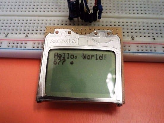
The Nokia 5110 is a basic graphic LCD screen for lots of applications. It was originally intended to be used as a cell phone screen. This one is mounted on an easy to solder PCB.
It uses the PCD8544 controller, which is the same used in the Nokia 3310 LCD. The PCD8544 is a low power CMOS LCD controller/driver, designed to drive a graphic display of 48 rows and 84 columns. All necessary functions for the display are provided in a single chip, including on-chip generation of LCD supply and bias voltages, resulting in a minimum of external components and low power consumption. The PCD8544 interfaces to microcontrollers through a serial bus interface.It uses the PCD8544 controller, which is the same used in the Nokia 3310 LCD. The PCD8544 is a low power CMOS LCD controller/driver, designed to drive a graphic display of 48 rows and 84 columns. All necessary functions for the display are provided in a single chip, including on-chip generation of LCD supply and bias voltages, resulting in a minimum of external components and low power consumption. The PCD8544 interfaces to microcontrollers through a serial bus interface.
Display OverviewThe Pinout
To interface with and power the graphic LCD, there are two, parallel 8-pin headers above and below it.
Pinout Table :Pinout Table :
Pin Number | Pin Label | Pin Function |Input/Output
- 1 | VCC | Positive power supply | Input
- 2 | GND | Ground | Input
- 3 | SCE | Chip select | Input
- 4 | RST | Reset | Input
- 5 | D/C | Mode select | Input
- 6 | DN(MOSI) | Serial data in | Input
- 7 | SCLK | Serial clock | Input
- 8 | LED | LED backlight supply | Input
Power Supplies
There are two different supply voltages on the LCD. The most important supply voltage – VCC – supplies the logic circuits inside the LCD. The datasheet states this should be between 2.7 and 3.3V. In a normal state, the LCD will consume about 6 or 7mA.
The second voltage supply is required for the LED backlights on the board. If you were to remove the LCD from the PCB (not that you should, or need to), you’d see that these are backlights in their simplest form – four white LEDs spaced around the edges of the board. You may also notice that there aren’t any current limiting resistors.
This means you have to be careful with this voltage supply. Either stick a current limiting resistor in series with the ‘LED’ pin, or limit the supply to 3.3 V max. The LEDs can pull a lot of current! With nothing to limit them, they’ll pull about 100mA at 3.3 V.
The Control Interface
Built into this LCD is a Philips PCD8544 display controller, which converts the massive parallel interface of the raw LCD to a more convenient serial one. The PCD8544 is controlled through a synchronous serial interface similar to SPI. There are clock (SCLK) and data (DN) input lines, and an active-low chip select (SCE) input as well.
On top of those three serial lines, there is another input – D/C – which tells the display whether the data it’s receiving is a command or displayable data.
For a list of commands, check out the “Instructions” section of the PCD8544 datasheet (page 11). There are instructions to enable clearing of the display, inverting the pixels, powering it down, and more.
Hardware Assembly & HookupAssembly
To “assemble” the LCD, you’ll need to solder something to one (or both) of the 8-pin headers. There are plenty of options available here. To make the LCD breadboard-compatible, straight or right-angle male headers can be soldered in.
Otherwise, wires or other connectors can be soldered to the display pins.Otherwise, wires or other connectors can be soldered to the display pins.
Hookup
For the data transmission pins – SCLK and DN(MOSI) – we’ll use the Arduino’s hardware SPI pins, which will help to achieve a faster data transfer. The chip select (SCE), reset (RST), and a data/command (D/C) pins can be connected to any digital I/O pin. Finally, the LED pin should be connected to a PWM-capable Arduino pin, so we can dim the backlight as we please.
Unfortunately, the LCD has a maximum input voltage of 3.6V, so we can’t hook up a standard 5V Arduino straight to it. We need to shift levels. This leads us to a few options for hookup:
- Direct Connect
The easiest hookup is to connect the Arduino pins directly to the LCD.
This setup can work for 5V Arduino’s, ignoring the 3.6V limit on the VCC and data lines. It works. But it may decrease your LCD’s life.
- Limiting Resistors
Sticking resistors in-line with the data signals is a cheap, and easy way to add some protection to the 3.3V lines. If you have an Arduino Uno (or similar 5V ‘duino) and some 10kΩ and 1kΩ resistors lying around, try this:
The pins are connected the same as in the above example, however each signal has an inline resistor. There are 10kΩresistors with the SCLK, DN, D/C, and RST pins. A 1kΩ resistor with SCE. And the 330Ω resistor remains between pin 9 and the LED pin.
- Level Converters
If you can spend some more money, then, a third option for hookup is to use actual level converters to switch between 5V and 3.3V. Boards like the Bi-Directional Logic Level Converter is perfect for something like this.
Unfortunately, the LCD has five 3.3V signal inputs and the level shifters only have four channels. If you want to keep the circuit to a single shifter, you can permanently tie RST high (through a 10kΩ resistors), and run the other signals through the shifter. You lose remote reset capability, but the rest of the control remains.
Example CodeWith the hardware all hooked up, we’re ready to upload a sketch and start drawing on the LCD!
Once uploaded to your Arduino, the sketch will begin by running the demo – a set of basic animations and graphics functions. To begin, we’ll draw some random pixels on the screen (“It’s full of stars…”). Then we’ll move on to examples of drawing lines, rectangles, and circles. Throughout there are examples of drawing characters and strings. Finally the demo closes out with an homage to a monochrome comic which seems a perfect fit for this little monochrome LCD.
This is a demo of drawing bitmaps on the screen, which is one of the more rewarding tasks we can accomplish with the ‘duino/LCD combo.is a demo of drawing bitmaps on the screen, which is one of the more rewarding tasks we can accomplish with the ‘duino/LCD combo.
After the demo runs its course, the sketch will enter into a serial echo mode. Open the serial monitor (set the baud rate to 9600 bps), and type stuff over to the Arduino. It should start printing everything you send it onto the LCD.
Drawing BitmapsIf the last demo has you chomping at the bit to design your own 84x48 bitmaps and display them, continue reading through this project. I’ll show you how to scale and import a bitmap, then compile it into your Arduino code and send it to the LCD, so you can have your own, silly graphic.
Find/Make/Modify a Bitmap
To begin, find a bitmap image that you’d like to print to the LCD. 84x48 monochrome pixels doesn’t give you a lot of room, but you can still get some fun stuff on there. Here are a few examples:
After you’ve picked an image, you’ll need to massage it to make it both monochrome (2-bit color) and 84 x 48 pixels. Most standard image editors can help with this. For Windows users, Paint is all you need to scale the image. Then save it as a monochrome bitmap.
Convert Bitmap to Array
The next step is converting that regular image file to a 504-byte array of char .There are a number of programs that can help with this around the web. We recommend LCD Assistant.
To load up an image in LCD Assistant, go to File > Load Image. A preview of the image should open up, make sure it’s the right size – 84 pixels wide, 48 pixels tall. Also make sure the Byte orientation is set to Vertical and the Size endianness is set to Little. The rest of the default settings (8 pixels/byte, etc.) should already be set correctly:
Then go to File > Save output to generate a temporary text file. Open that text file to have a look at your shiny new array. You’ll need to modify the type of the array to be just a char. Also make sure the array has the proper naming conventions (no dashes, don’t start with a number, etc.).
Import the sketch and draw
With that array created, copy the entire table over to your Arduino sketch.
// ...LCD definitions, variables, and bitmap array defined above.
void setup()
{
 lcdBegin(); // This will setup our pins, and initialize the LCD
 setContrast(60); // Good values range from 40-60
 setBitmap(flameBitmap); // flameBitmap should be replaced with the name of your BMP array
 updateDisplay();  // Update the display to make the array show up.
}
void loop()
{
}
// LCD control and graphics functions defined below...
Fun stuff! Now you can overlay text, or draw on on your bitmap. You can even try importing multiple graphics to create animations!
_kcYbIze1kU.png)


_3u05Tpwasz.png?auto=compress%2Cformat&w=40&h=40&fit=fillmax&bg=fff&dpr=2)
_kcYbIze1kU.png)
Comments